Rotor blades of wind turbines with a rated power of 20 MW and more will reach lengths of at least 150 m. The ongoing trend of low induction rotors will result in ultra-slender designs. Due to the dimensions of such rotor blades, a structural design taking into account the composite material peculiarities and exploiting their full lightweight potential becomes increasingly important. Besides, precise knowledge on the loads acting on the rotor blade is inevitable for providing enough stiffness, strength, and lifetime. In order to obtain maximum accuracy in determining loads, cross-sectional deformations of the blade, the so-called “breathing”, needs to be taken into consideration in the structural design, as it may trigger aero-elastic couplings. Moreover, the gravitational loads scale in a progressively non-linear manner with the rotor length. Hence, the usual, experience-based, and evolutionary approach for further developments of existing turbines cannot be the expedient solution for turbines beyond 20 MW rated power. An economically feasible design of rotor blades of that power class can only be realised through a rapid leap. This can be enabled by efficient optimisation methods incorporating an extended parameter space and the consideration of the governing local effects already in the modelling stage. Hence, the subproject B03 has the following research goals:
- Development of new formulations of a gradient-based optimisation problem for the structural design of rotor blades that consider an extended design parameter space in order to enable evaluations of novel designs and material combinations.
- Development of fundamental knowledge considering the requirements for cross-sectional deformations within the cross-section planes, the effects of such deformations on the turbine dynamics and the resulting loads, and their impact on the structural design of the rotor blade.
Optimisation of the structural design
New designs and material combinations can help to carry the extraordinarily high loads and transfer them to subsequent turbine components. For that purpose, new formulations of the optimisation problem are required with parameterisations and constraints not available to date. These have to exploit the specific anisotropic properties of fibre composite materials and have to enable the evaluation of new designs, e.g., the inclusion of additional discrete stiffeners. Besides, manufacturability plays an important role as well and has to be guaranteed.
A classical structural design of a rotor blade is depicted in Figure 1. New structural topologies with additional discrete stiffening are to be integrated in the optimisation framework as well as new concepts of material combinations. The new design process envisaged in the sub-project B03 is described in more detail below. The optimisation problem needs to be formulated in such a way that a large number of design variables can be treated at minimum computational cost. Fundamental knowledge is to be derived on how the parameterisation of the blade has to be done, so that discrete variables of the structural topology or material combinations can be described by continuous and convex functions enabling a computationally efficient gradient-based optimisation framework.
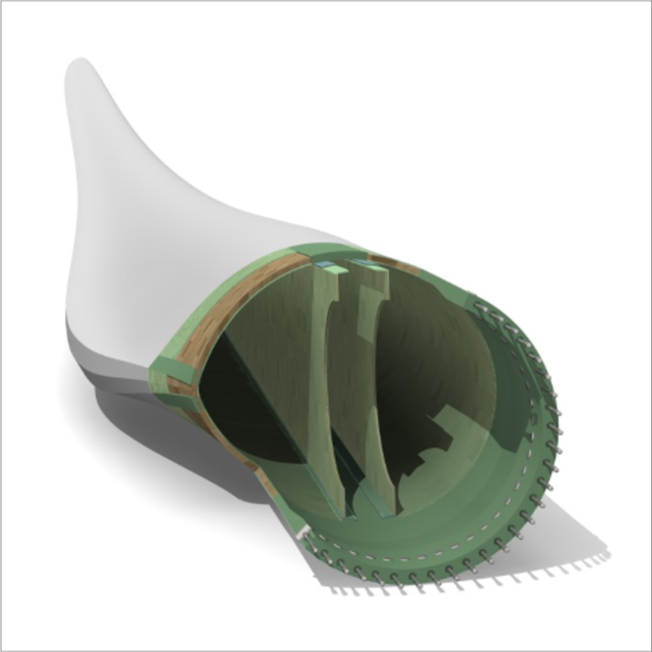 ©
Fraunhofer IWES / Felix Klaenfoth
©
Fraunhofer IWES / Felix Klaenfoth
Moreover, strength and deformation constraints need to be formulated taking into account manufacturability, so that requirements from the 3D structural response can be treated in a cross-section-based optimisation strategy.
Investigation of geometrically non-linear cross-sectional deformations
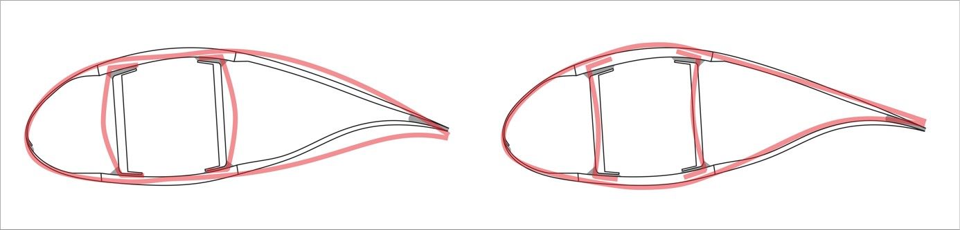
Rotor blades experience cyclic deformations of their cross-sections within the cross-section planes during operation. This geometrically non-linear effect is called “breathing” and is depicted in Figure 2. It is especially observed in the highly loaded inboard region of very large, slender, and flexible blades. The influence of breathing on the structural dynamics of rotor blades has not been studied extensively yet. There is a lack of fundamental knowledge on how breathing can be accounted for in the simulation of the entire turbine system and how it can be included in a structural optimisation environment.
To fill this gap, simulation methods that enable the quantification of breathing are to be investigated, implemented, and applied in the sub-project B03. These will be transferred to a beam model that accounts for the significant effects of breathing on the 3D structural response and the aerodynamics of the blade. By integrating the new beam model into the Digital Twin (see subproject Z01), more accurate load sets can be determined and included in the structural optimisation procedure, as described in the new design process below. In this way, the impact of breathing on the turbine dynamics and the structural design can be evaluated, integrating also new design topologies.
 ©
LUH IWES / Claudio Balzani
©
LUH IWES / Claudio Balzani
New design process
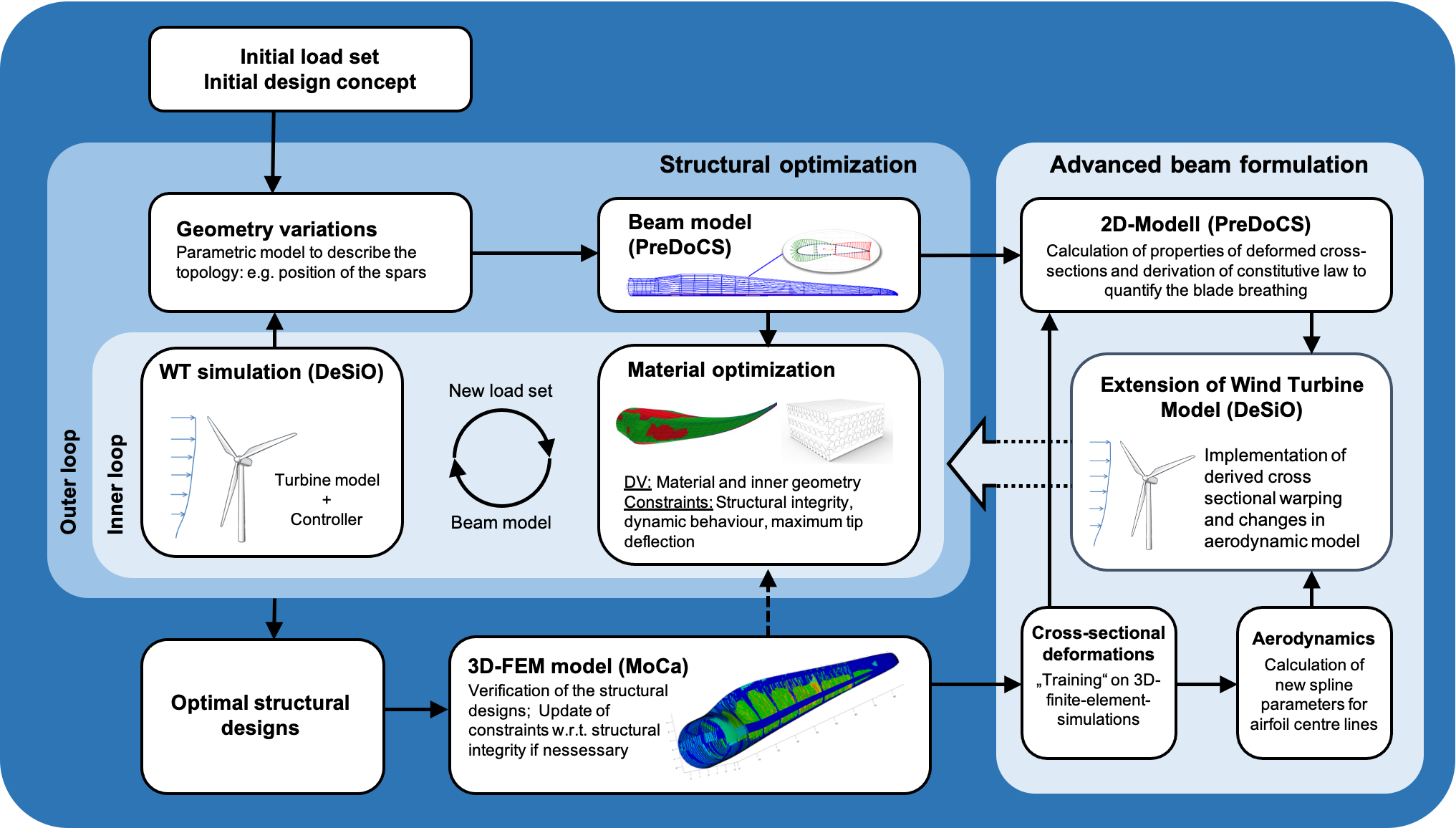
The aim of this sub-project is to set up a new structural design process that includes both the new optimisation method and the more accurate load sets incorporating the breathing of the rotor blade. Figure 3 shows the framework of the envisaged new design process. In the first step, a parametric model of the rotor blade is derived on the basis of the initial design concept. From that, a beam model is deduced that includes all design variables that are required for the optimisation of the structural topology and material composition. The inner loop comprises the optimisation of the material composition and the loads simulation. Therein, constraints are employed such as appropriate failure criteria as well as global criteria for the static and aeroelastic turbine behaviour, e. g., maximum tip deflection. After convergence of the inner loop, geometrical variations (i.e., variations in the structural topology) are accounted for in the outer loop, which lead to an update of the beam model. Then, the inner loop is repeated, and so forth, until the overall structural design converges to an optimum.
For the most promising design candidates, 3D finite element models are built and the respective simulations are carried out. The aim is to account for additional effects from the 3D response of the blade, e.g., buckling or redistributions of stresses due to 3D deformations. If failure criteria are violated, the constraints in the optimisation procedure need to be updated and the optimisation is repeated. The 3D models are further utilised to investigate cross-sectional deformations in the context of breathing, as described above. Based on a variety of load cases and their influence on the blade’s deformations, a functional relationship between loads and cross-sectional properties (e.g., moments of inertia) is to be deduced and implemented in the Digital Twin. In this way, the Digital Twin will be used for the determination of new and more accurate load sets that can be utilised in the design optimisation of the blade.
 ©
LUH IWES / DLR
©
LUH IWES / DLR
Subproject Management
30167 Hannover
Institut für Faserverbundleichtbau und Adaptronik | Funktionsleichtbau
Lilienthalplatz 7
38108 Braunschweig
Institut für Faserverbundleichtbau und Adaptronik | Funktionsleichtbau
Lilienthalplatz 7
38108 Braunschweig
Staff
30167 Hannover
Institut für Faserverbundleichtbau und Adaptronik | Funktionsleichtbau (FA-FLB) | c/o ZAL TechCenter Hein-Saß-Weg 22
21129 Hamburg
Institut für Faserverbundleichtbau und Adaptronik | Funktionsleichtbau (FA-FLB) | c/o ZAL TechCenter Hein-Saß-Weg 22
21129 Hamburg